Interrupt(8):callout for cascaded interrupts

SDMA interrupt entry is added in init_intrinfo().

 Identify SDMA interrupt source.
 *
 * Returns interrupt number in r4
 * -----------------------------------------------------------------------
 */
CALLOUT_START(interrupt_id_omap4_sdma, 0, interrupt_patch_sdma)
	/*
	 * Get the interrupt controller base address (patched)
	 */
	mov		ip,     #0x000000ff
	orr		ip, ip, #0x0000ff00
	orr		ip, ip, #0x00ff0000
	orr		ip, ip, #0xff000000

	/*
	 * Read Interrupt Mask and Status
	 */
	ldr		r3, [ip, #SDMA_IRQSTATUS]		// Status
	ldr		r2, [ip, #SDMA_IRQENABLE]		// Mask
	and		r3, r3, r2

	/*
	 * Scan for first set bit
	 */
#if 0
	mov		r4, #32
	mov		r1, #1

0:
	subs	r4, r4, #1
	blt		1f
	tst		r3, r1, lsl r4
	beq		0b
#else
	clz		r4, r3
	rsbs	r4, r4, #31
	blt		1f
	mov		r1, #1
#endif
    /*
	 * Mask the interrupt source
	 */
	mov		r1, r1, lsl r4
	bic		r2, r2, r1
	str		r2, [ip, #SDMA_IRQENABLE]
	ldr		r2, [ip, #SDMA_IRQENABLE]

	/*
	 * Clear interrupt status
	 * 09.17.2014: clearing the staus bit is moved to the eoi-callout since the status bit related
	 * to a channel can only be claered if the channel status register of the associated
	 * channel is cleared. Clearing the csr can't be done in a generic way here because the attached
	 * isterrupt service routines need to know the interrupt reason (block, fram, drop etc. ...)
	 */
	//str		r1, [ip, #SDMA_IRQSTATUS]
1:
CALLOUT_END(interrupt_id_omap4_sdma)

/*
 * -----------------------------------------------------------------------
 * Acknowledge specified SDMA interrupt
 *
 * On entry:
 *	r4 contains the interrupt number
 *	r7 contains the interrupt mask count
 * -----------------------------------------------------------------------
 */
CALLOUT_START(interrupt_eoi_omap4_sdma, 0, interrupt_patch_sdma)
	/*
	 * Get the interrupt controller base address (patched)
	 */
	mov		ip,     #0x000000ff
	orr		ip, ip, #0x0000ff00
	orr		ip, ip, #0x00ff0000
	orr		ip, ip, #0xff000000

    /*
     * Only unmask interrupt if mask count is zero
     */
	teq		r7, #0
	bne		0f
	
	/*
	 * Clear interrupt status
	 * see comment in the id-callout
	 */
	mov		r2, #1
	mov		r2, r2, lsl r4
	str		r2, [ip, #SDMA_IRQSTATUS]

	ldr		r1, [ip, #SDMA_IRQENABLE]
	orr		r1, r1, r2
	str		r1, [ip, #SDMA_IRQENABLE]

0:
CALLOUT_END(interrupt_eoi_omap4_sdma)
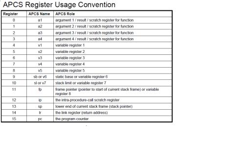
ARM assembly language

Parameter passing

  1. use registers for first 4 parameters (r0, r1, r2, r3);
  2. use stack beyond;
  3. return using r0.
  4. Functions can freely modify registers R0–R3 and R12. If a function needs to use R4 through R11, it is necessary to push their current register values onto the stack, use the register, and then pop the old value off the stack before returning.

Variable declaration

.balign 4      //  ensure the next address will start a 4-byte boundary.

myvar1: .word 3  // .word directive states that the assembler tool should emit the value of the argument of the directive as a 4 byte integer. the initial value of the variable is 3.

Instructions

ANDS {Rd,} Rn, Rm

ORRS {Rd,} Rn, Rm  ==> inclusive OR           Used to set bits

EORS {Rd,} Rn, Rm  ==> exclusive OR (only true if the corresponding bits differ)

BICS {Rd,} Rn, Rm  == >                           Used to clear bits

TEQ{cond} Rn, Operand2  == > same as EORs, except that the result is discarded ==> use for check if the bits of Rn is same as Operand2, result is 0 if same; result is 1 if different.

BEQ label                        ==> branch if equal to 0; used in conjunction with the previous instruction

MOV Rd, #expr

MOV Rd, Rm

MVN Rd, Rm  ==> takes the value in Rm, performs a bitwise logical NOT operation on the value, and places the result in Rd.

NEG Rd, Rm   ==> takes the value in Rm, multiplies it by –1, and places the result in Rd.

MOV r0, r0, LSL #1   ==> r0 << 1


arm_regs

syspage(3): callouts

In order for the Neutrino microkernel to work on all boards, all hardware-dependent operations have been factored out of the code — Known as kernel callouts.

Callouts:

  • are provided by the startup program.
  • get overwritten when the kernel starts up.
    • Startup program will copy the callouts (the code between CALLOUT_START and CALLOUT_END)from the startup program into the system page and after this, the startup memory (text and data) is freed.
  • allow you to “hook into” the kernel and gain control when a given event occurs.
    • The callouts operate in an environment similar to that of an interrupt service routine — you have a very limited stack, and you can’t invoke any kernel calls (such as mutex operations, etc.).
  • must be Position-independent
    • reason: they won’t be in the location that they were loaded in, they must be coded to be position-independent.
    • how: be coded in assembler
  • No static read/write storage
    • if needed, you can make a small storage available for it, by using the patcher routines and the 2nd parameter to CALLOUT_START. see the example below on how it works.
  • For all but two of teh routines (interrupt_id(), interrupt_eoi), the kernel invokes the callouts with the normal function-calling conventions
    • For performance reasons, the kernel intermixes id() and eoi() directly with kernel code.

Types of Callouts

  • debug interface
  • clock/timer interface
  • interrupt controller interface
    • 3 callouts for interrupt controller interface: mask(), unmask(), config().
    • 2 callouts as code stubs: id(), eoi()
    • Each group of callouts (i.e. id, eoi, mask, unmask) for each level of interrupt controller deals with a set of interrupt vectors that start at 0 (zero-based).
  • cache controller interface
  • system reset
  • power management

Callout macros, defined in “callout.ah”

rw_intr: .word 8

CALLOUT_START(interrupt_id_gic, rw_intr, patch_id)

  •   1st parameter: name of the callout routine
  • 2nd parameter: address of a 4-byte variable that contains the amount of  read/write storage the callout needs.
  • 3rd parameter: either a zero or the address of a patcher() routine.

CALLOUT_END(interrupt_id_gic)

“patching” the callout code

  • make it possible for the same callout routine to be used on the different boards, where the device might be at different locations.
  • a patcher() is invoked immediately after the callout has been copied to its final resting place.
  • make read-write storage available for the callout, when used together with 2nd parameter of CALLOUT_START.
    • “rw_intr: .word 8″ tells the startup library that the routine needs 8 bytes of read/write storage.
    • The startup library allocates space at the end of the system page and passes the offset to it as the rw_offset parameter of the patcher routine.
    • The patcher routine then modifies the initial instruction of the callout to the appropriate offset.
    • While the callout is executing, the t3 register will contain a pointer to the read/write storage.

syspage(2)-intrinfo

intrinfo is automatically filled in by init_intrinfo()

Note:

  1. struct startup_intrinfo is defined and used by startup code. the public definition is in sys/syspage.h.
  2. Each group of callouts (i.e. id, eoi, mask, unmask) for each level of interrupt controller deals with a set of interrupt vectors that start at 0 (zero-based). Interrupt vector numbers are passed without offset to the callout routines. The association between the zero-based interrupt vectors the callouts use and the system-wide interrupt vectors is configured within the startup-intrinfo structures.
  3. flags:
    • INTR_GENFLAG_LOAD_SYSPAGE 
      • Before the interrupt id or eoi code sequence is generated, a piece of code needs to be inserted to fetch the system page pointer into a register so that it’s usable within the id code sequence.
    • INTR_GENFLAG_LOAD_INTRMASK
      • Used only by EOI routines for hardware that doesn’t automatically mask at the chip level.
      • When the EOI routine is about to reenable interrupts, it should reenable only those interrupts that are actually enabled at the user level (e.g. managed by the functions InterruptMask() and InterruptUnmask()). When this flag is set, the existing interrupt mask is stored in a register for access by the EOI routine. A zero in the register indicates that the interrupt should be unmasked; a nonzero indicates it should remain masked.
struct intrinfo_entry {
	_Uint32t vector_base; // base number of the logical interrupt/vector numbers(IRQs) that programs will use
	_Uint32t num_vectors; // the number of the vectors
	_Uint32t cascade_vector;// the logical IRQ number for cascaded interrupts
	_Uint32t cpu_intr_base;
	_Uint16t cpu_intr_stride;
	_Uint16t flags;
	struct __intrgen_data	id;
	struct __intrgen_data	eoi;
	_SPFPTR(int, mask, (struct syspage_entry *, int));
	_SPFPTR(int, unmask, (struct syspage_entry *, int));
	_SPFPTR(unsigned, config, (struct syspage_entry *, struct intrinfo_entry *, int));
	_Uint32t				spare[4];
};

A piece of sample code:

// Adding main ARM GIC Controller
const static struct startup_intrinfo intrs[] =
{
    {
        .vector_base      = _NTO_INTR_CLASS_EXTERNAL, // (0x0000UL << 16)
        .num_vectors      = 32+192, // including SGIs, PPIs, SPIs
        .cascade_vector   = _NTO_INTR_SPARE, // (0x7FFFFUL << 16) | 0xFFFF
        .cpu_intr_base    = 0,
        .cpu_intr_stride  = 0,
        .flags            = 0,
        .id               = { INTR_GENFLAG_LOAD_SYSPAGE, 0, &interrupt_id_gic},
        .eoi              = { INTR_GENFLAG_LOAD_SYSPAGE | INTR_GENFLAG_LOAD_INTRMASK, 0, &interrupt_eoi_gic},
        .mask             = &interrupt_mask_gic,
        .unmask           = &interrupt_unmask_gic,
        .config           = &interrupt_config_gic,
        .patch_data       = NULL,
    }
};
// Adding System DMA interrupt cascaded into OMAP54XX_SDMA_IRQ_0 only
static struct startup_intrinfo sdmaintrs[] = 
{
    {
        .vector_base      = 256,
        .num_vectors      = 32,
        .cascade_vector   = OMAP54XX_SDMA_IRQ_0,
        .cpu_intr_base    = 0,
        .cpu_intr_stride  = 0,
        .flags            = 0,
        .id               = { 0, 0, &interrupt_id_omap4_sdma },
        .eoi              = { INTR_GENFLAG_LOAD_INTRMASK, 0, &interrupt_eoi_omap4_sdma },
        .mask             = &interrupt_mask_omap4_sdma,
        .unmask           = &interrupt_unmask_omap4_sdma,
        .config           = 0,
        .patch_data       = &sdma_base,
    },
};
init_intrinfo()
{
    initialize the interrupt controller; // See the sample code in Interrupt(2): ARM Interrupt Controller
    add_interrupt_array(intrs, sizeof(intrs));
    disable all SDMA channel interrupts, and clear all channel statuses; 
    add_interrupt_array(sdmaintrs, sizeof(sdmaintrs));
}

syspage(1)

System page: an in-memory data structure which stores the information about the system, e.g. processor type, the location and size of available system RAM.

  • the system page is initialized by the startup program.
  • the kernel as well as applications can access this information as a read-only data structure.
  • struct syspage_entry is defined in <sys/syspage.h>

struct syspage_entry {
uint16_t size;
uint16_t total_size;
uint16_t type;          // ARM, MIPS, PPC, SH4, or X86
uint16_t num_cpu;
syspage_entry_info system_private;
syspage_entry_info asinfo;
syspage_entry_info hwinfo;
syspage_entry_info cpuinfo; //  CPU type, speed, capabilities, performance, and cache sizes, etc
syspage_entry_info cacheattr;
syspage_entry_info qtime;  // get a timestamp via: SYSPAGE_ENTRY(qtime)->nsec
syspage_entry_info callout; // allow you to “hook into” the kernel and gain control when a given event occurs.
syspage_entry_info callin;
syspage_entry_info typed_strings;
syspage_entry_info strings;
syspage_entry_info intrinfo;  // information about the interrupt system
syspage_entry_info smp;
syspage_entry_info pminfo;
union {
struct x86_syspage_entry x86;
struct ppc_syspage_entry ppc;
struct mips_syspage_entry mips;
struct arm_syspage_entry arm;
struct sh_syspage_entry sh; }}


Interrupt(7): Init & Attach/Detach in OS

All the interrupt information is generated in startup, store in syspage, then gets copied to one area.

syspage_init() gets the pointers to each syspage entry

{

	qtimeptr = SYSPAGE_ENTRY(qtime);

	intrinfoptr = SYSPAGE_ENTRY(intrinfo);
	intrinfo_num = _syspage_ptr->intrinfo.entry_size / sizeof(*intrinfoptr);

	calloutptr = SYSPAGE_ENTRY(callout);

}

interrupt_init()

  1. initializes some interrupt variables based on syspage intrinfo: here we use  intrinfo initialized here as an example:
    • num_external_level =  (32 + 192) + 32 = 256  ==>the sum of all iip->num_vectors
    • interrupt_level[] is an array of struct interrupt_level, the size is: 256+ NUM_HOOK_RTNS.
      • then let interrupt_level points at first external level: interrupt_level += NUM_HOOK_RTNS;
      • ilp: each interrupt entry (GIC, SDMA, GPIO, etc) in syspage
        • ilp->level_base = vector base of this entry;
        • ilp->info = the pointer to the start of the interrupt entry
        • for regular interrupt entry,
          • ilp->mask_count = 1;
          • ilp->cascade_level = -1
        • for cascaded entry,
          • ilp->cascade_level = vector base of this entry;
          • ilp->info->unmask()
          • ilp->mask_count = 0;
  2. write the interrupt entries to the processor/CPU vector table: see cpu_interrupt_init() for ARM

 interrupt_attach(level, (handler), …). there is a global variable “count” in this function:

  • find the interrupt_level: ilp = &interrupt_level[level];
  • count the number of existing interrupt entries which have attached to this level/IRQ;
  • allocate an interrupt entry “itp” by calling object_alloc().
    • itp->thread = current thread;
    • itp->level = level; // IRQ number
    • itp->handler = handler
  • add itp to the interrupt vector: id= vector_add(&interrupt_vector, itp, 0);
    • itp->id = id;
  • add itp to the table of existing interrupt entries for that level.
  • if count == 0 (the first handler gets installed), call interrupt_unmask(level, NULL).

interrupt_detach(level, handler)

  • remove the entry from the interrupt vector: itp = vector_rem();
  • if there are no more interrupt entries attached to this interrupt_level[level],
    • disable the interrupt: interrupt_mask();
    • interrupt_level[level].mask_count = 1;
    • itp->mask_count = 0;
  • if there is still interrupt enties for this level, set need_maskcount_check = 1.
  • remove interrpt handler from interrupt table.

interupt_unmask() —> unmask() callout

Kernel calls

InterruptAttach(): Attach an interrupt handler to an IRQ. This call automatically enable (unmask) the interrupt.

  • The first process to attach to an interrupt unmasks the interrupt. When the last process detaches from an interrupt, the system masks it.
  • If the thread that attached the interrupt handler terminates without detaching the handler, the kernel does it automatically — different behaviorNTO_INTR_FLAGS_PROCESS is set!
  • Processor interrupts are enabled during the execution of the handler. Don’t attempt to talk to the interrupt controller chip. The operating system issues the end-of-interrupt command to the chip after processing all handlers at a given level.

  • a few flags:
    • NTO_INTR_FLAGS_END
      • for shared interrupt.
      • adds the handler at the end of any existing handlers (default is to add in front of existing handlers).
    • NTO_INTR_FLAGS_PROCESS
      • associates the interrupt handler with the process instead of the attaching thread.
      • The interrupt handler is removed when the process exits, instead of when the attaching thread exits.
    •  _NTO_INTR_FLAGS_TRK_MSK
      • _NTO_INTR_FLAGS_TRK_MSK flag and the id argument to InterruptMask() and InterruptUnmask() let the kernel track the number of times a particular interrupt handler or event has been masked. Then, when an application detaches from the interrupt, the kernel can perform the proper number of unmasks to ensure that the interrupt functions normally. This is important for shared interrupt levels.

Note: in my libraries, all the interrupts are attached using “_NTO_INTR_FLAGS_PROCESS” and “_NTO_INTR_FLAGS_TRK_MSK” flag.

InterruptDetach(id)

  • These kernel calls detach the interrupt handler specified by the id argument. If, after detaching, no thread is attached to the interrupt, then the interrupt is masked off.The thread that detaches the interrupt handler must be in the same process as the thread that attached it.

Interrupt(6): interrupt handling in OS

When an interrupt occurs,
  • Interrupt controller asserts one signal to the processor.
  • the CPU jumps to the vector table, looking for the handler for that type of exception.
  • the handler (pieces of assembly code, generated by cpu_init_interrupt())
    • intr_entry_start          // services/system/ker/arm/kernel.S
      • save registers, branch to id()
    • id()
      • acknowledge the GIC by reading the acknowledge register.
      • mask/disable the interrupt ID in GIC.
      • return interrupt number in r4.
    • if it is cascaded interrupt, branch to cascaded interrupt id()
      • find the interrupt source by reading registers
      • mask/disable the interrupt source in the controller
      • return the interrupt ID in r4
    • intr_process_queue
      • dispatch the interrupt to the appropriate handlers, — branch to interrupt().
      • This passes the INTRLEVEL in r8.
    • interrupt(): defined in services/system/ker/arm/interrupt.c
      • interruptEnable(); what’s the purpose of doing this?
      • find ilp->queue, and look for the handler for each entry in that queue
        • if there is a handler, execute it;
          • if the event returned by the handler is not NULL,  call intrevent_add();
        • if there is no handler,
          • interrrupt_mask(isr->level, isr);
          • intrevent_add();
      • InterruptDisable();
    • if it is cascaded interrupt, and if it is necessary (another interrupt ID), call id() callout again ?????
    • eoi()
    • intr_done
      • return from interrupt handling.

note:

  1. the input of eoi is a interrupt id. so it is only possible to unmask one interrupt.
  2. mask_count is for a particular Interrupt Level (IRQ)
    • The mask count increases for every interrupt handler you have attached to the same vector. So when you attach an interrupt handler the Kernel will call the unmask callout (to enable the interrupt vector) and increment the mask count. When the interrupt goes off the ID callout occurs and masks/disables the interrupt and then calls each handler that is attach on that vector. When each interrupt handler completes the mask count is  decremented and the eoi callout is called. The last handler to exit will cause the mask count to reach 0 and the eoi will unmask/re-enable the interrupt.
  3. If there are two SDMA channel complete at the same time – two bits are set in IRQSTATUS. My understanding is, based on the reading of the callout code, id() will be entered twice, so does the eoi().
    • the first time sdma_id() is called, there are two bits set in IRQSTATUS, the code scan for first set bit, and disable the corresponding bit in IRQENABLE.
    • when eoi() is entered, it checks if  mask_count is zero (all handlers for that IRQ have exited). if yes, clear the bit in IRQSTATUS, and set the bit in IRQENABLE.
    • the 2nd id() is entered, there is only one bit left in IRQSTATUS.


Interrupt(5): enable & disable & mask & unmask

InterruptEnable()  — enables all hardware interrupts. can be called from a thread or from an interrupt handler.

__asm {
MRS r1, CPSR      —> copy CPSR to r1
BIC r1, r1, #0x80  —> set bit 7 to 0
MSR CPSR_c, r1   –> copy the modified value back to CPSR
}

InterruptDisable() — disable all hardware interrupts.

__asm {
MRS r1, CPSR      —> copy CPSR to r1
ORR r1, r1, #0x80  —> set bit 7 to 1
MSR CPSR_c, r1   –> copy the modified value back to CPSR
}

Note:

  1. interruptEnable() and InterruptDisable() only work on single processor hardware. Use InterruptLock() and InterruptUnlock() pair, which can be used on either multi-processor or single processor hardware
  2. InterruptLock() calls InterruptDisable() first.
  3. InterruptUnlock() calls Interruptenable() at the end.

InterruptLock(spinlock) — Guards a critical section by locking the specified spinlock.

  • InterruptLock() protects access to shared data structures between an interrupt handler and the thread that owns the handler.
  • InterruptLock() tries to acquire the spinlock (a variable shared between the interrupt handler and a thread) while interrupts are disabled. The code spins in a tight loop until the lock is acquired. It’s important to release the lock as soon as possible.
  • the thread must have the PROCMGR_AID_IO ability enabled.

    It’s important to release the lock as soon as possible.

  • If spinlock isn’t a static variable, you must initialize it by calling:
    memset( spinlock, 0, sizeof( *spinlock ) );

InteruptMask(int IRQ, int id)   Disable a hardware interrupt. id is the interrupt id returned by InterruptAttach().

  • only calls mask() callout if the current ip->mask_cont == 0;
    • otherwise, only increase the mask_count for that intetrupt level: ilp->mask_count++;
  • if the parameter id (itp) is not NULL, ++ itp->mask_count.

note: The id is ignored unless you use the _NTO_INTR_FLAGS_TRK_MSK flag when you attach the handler.

What’s behind InterruptMask() call?

the kernel will  either look for the corresponding “mask” function for this interrupt in SYSPAGE area (if in_interrupt() returns true), or call __interruptMask

in QNX, it is usually implemented as a callout. For ARM based processor,

  • mask() callout will write to ICDICER (distributer Interrupt Clear-Enable register);
  • unmask() callout will write to ICDISER (distributer Interrupt Set-Enable register).

Interrupt(4): Exception handling & Vector Table

Exceptions occur when:

  • externally generated interrupts
  • an attempt by the processor to execute an undefined instruction
  • accessing privileged operating system functions.

When an exception occurs, control passes through an area of memory called the vector table. This is a reserved area usually at the bottom of the memory map. Within the table one word is allocated to each of the various exception types. This word contains either a branch instruction or, in the case of ARMv6-M and ARMv7-M, an address to the relevant exception handler.

pge1358787014824

A vector table consists of a set of ARM instructions that manipulate the PC (i.e. B, MOV, and LDR). These instructions cause the PC to jump to a specific location that can handle a specific exception or interrupt.

Example:  Typical vector table using a literal pool

                AREA vectors, CODE, READONLY
                ENTRY
Vector_Table
                LDR pc, Reset_Addr
                LDR pc, Undefined_Addr
                LDR pc, SVC_Addr
                LDR pc, Prefetch_Addr
                LDR pc, Abort_Addr
                NOP                    ;Reserved vector
                LDR pc, IRQ_Addr
FIQ_Handler
                ; FIQ handler code - max 4kB in size

Reset_Addr      DCD Reset_Handler
Undefined_Addr  DCD Undefined_Handler
SVC_Addr        DCD SVC_Handler
Prefetch_Addr   DCD Prefetch_Handler
Abort_Addr      DCD Abort_Handler
                DCD 0                  ;Reserved vector
IRQ_Addr        DCD IRQ_Handler
                ...
                END

The processor response to an exception

When an exception is generated, the processor performs the following actions:

  1. Copies the CPSR into the appropriate SPSR. This saves the current mode, interrupt mask, and condition flags.
  2. Switches state automatically if the current state does not match the instruction set used in the exception vector table.
  3. Changes the appropriate CPSR mode bits to:
    • Change to the appropriate mode, and map in the appropriate banked out registers for that mode.
    • Disable interrupts. IRQs are disabled when any exception occurs. FIQs are disabled when an FIQ occurs and on reset.
  4. Sets the appropriate LR to the return address.
  5. Sets the PC to the vector address for the exception.

Returning from an exception handler

The method used to return from an exception depends on whether the exception handler uses stack operations or not. In both cases, to return execution to the place where the exception occurred an exception handler must:

  • restore the CPSR from the appropriate SPSR
  • restore the PC using the return address from the appropriate LR.


the GIC signals an interrupt exception request to the processor.

gic_id() is executed, to read  ICCIAR to get the interrupt ID. — how kernel find gic_id()?

then gic_id() disables that interrupt in GIC.

for cascaded interrupt, sdma_id is exectured,

interrupt handler(s) are entered.

….


Interrupt(3): interrupt callouts (ARM GIC)

Registers:

  1. Interrupt Acknowledge Register (ICCIAR)
      • ICCIAR[12:10]: the processor(CPU) that requested the interrupt;
      • ICCIAR[9:0]: the interrupt ID
    • The processor reads this register to obtain the interrupt ID of the signaled interrupt.This read acts as an acknowledge for the interrupt.
    • A read of the ICCIAR returns the interrupt ID of the highest priority pending interrupt for the CPU interface,
      • The read returns a spurious interrupt ID of 1023 if any of the following apply:
        • Signalling of interrupts to the CPU interface is disabled
        • There is no pending interrupt on this CPU interface with sufficient priority for the interface to signal it to the processor.
  2. End of Interrupt Register (ICCEOIR)
    • A processor writes to this register to inform the CPU interface that it has completed its interrupt service routine for the specified interrupt.
    • The interrupt service routine on the connected processor must write to the ICCEOIR for every read of a valid Interrupt ID from the ICCIAR,
    • Writing to this register causes the GIC to change the status of the identified interrupt:
      • to inactive, if it was active
      • to pending, if it was active and pending.
  3. Interrupt Clear-Enable Registers (ICDICERn), n = 0 ~31
    • Writing 1 to a Clear-enable bit disables forwarding of the corresponding interrupt to the CPU interfaces.
  4. Interrupt Set-Enable Registers (ICDISERn)
    • Writing 1 to a Set-enable bit enables forwarding of the corresponding interrupt to the CPU interfaces.

id() callout:

  1. read ICCIAR reg to get the interrupt ID –> this is step 5 described in arm-interrupt-controller.
    • if  ICCIAR[9:0] is 0 (it might be SGI), write   ICCEOIR and exit id().
    • if ICCIAR[12:0} is set to 0x3FF, it is a spurious interrupt ID, exit id()
  2. disable interrupt source by writing to the corresponding bit in ICENABLERn.
  3. writes the interrupt ID to the ICCEOIR, to signal the completion — > step 6

eoi() callout:

  1. if Interrupt ID is 0, do nothing.
  2. if mask count is not zero, do nothing.
  3. if mask count is zero, enable interrupt source by writing to the corresponding bit in ISENABLERn

mask() callout: write to ICDICERn.

unmask() callout writes to ISDICERn

/*
 * -----------------------------------------------------------------------
 * Identify interrupt source.
 *
 * Returns interrupt number in r4
 * -----------------------------------------------------------------------
 */
CALLOUT_START(interrupt_id_gic, rw_intr, patch_id)
	mov		ip,     #0x000000ff		// RW data offset (patched)	
	orr		ip, ip, #0x0000ff00
	add		ip, r5, ip				// INTR_GENFLAG_LOAD_SYSPAGE specified

	ldr		r0, [ip, #OFF_GIC_CPU]	// cpu interface registers
	ldr		r1, [ip, #OFF_GIC_DIST]	// distributor registers

	/*
	 * Get interrupt ID and check for special cases:
	 * ID0    - used for IPI: immediately send eoi as we need src cpu to eoi
	 * ID1023 - spurious interrupt: set vector to -1
	 */
	ldr		r4, [r0, #ARM_GICC_IAR]
	bics	ip, r4, #ARM_GICC_IAR_SRCID   // defined as 0x1C00. r4 contains Interrupt ID
	streq	r4, [r0, #ARM_GICC_EOIR]   // if r4[9:0] is 0, write EOI.
	mov		r4, ip   // mov from ip to r4, Interrupt IDs?
	beq		0f
	mov		ip,     #0x0ff
	orr		ip, ip, #0x300
	teq		r4, ip
	mvneq	r4, #0     // if (r4 == 0x3FF), move -1 to r4
	beq		0f

	/*
	 * Mask the interrupt source
	 */
	and		r2, r4, #0x1f     // lower 5 bits of r4 --> r2
	mov		r3, #1
	mov		r3, r3, lsl r2	// 1 << r2 --> r3   ==> 1 << (id % 32)
	mov		r2, r4, lsr #5   // r4 << 5 --> r2  ==> get the index n
	mov		r2, r2, lsl #2   // r2 << 2 --> r2 ==> reg offset to GICD_ICENABLEERn
	add		r2, r2, #ARM_GICD_ICENABLERn		// ENABLE_CLR[id / 32]
	str		r3, [r1, r2]

	/*
	 * Send EOI to controller
	 */
	str		r4, [r0, #ARM_GICC_EOIR]
0:
CALLOUT_END(interrupt_id_gic)
 * On entry:
 *	r4 contains the interrupt number
 *	r7 contains the interrupt mask count
 * -----------------------------------------------------------------------
 */
CALLOUT_START(interrupt_eoi_gic, rw_intr, patch_rw)
	mov		ip,     #0x000000ff		// RW data offset (patched)	
	orr		ip, ip, #0x0000ff00
	add		ip, r5, ip				// INTR_GENFLAG_LOAD_SYSPAGE specified

	/*
	 * Special case: IPI interrupt (ID0) is never disabled
	 */
	teq		r4, #0    // if r4 == 0, the condition is false (0)
	beq		0f

	/*
	 * Only unmask interrupt if mask count is zero
	 */
	teq		r7, #0
	bne		0f

	ldr		r0, [ip, #OFF_GIC_DIST]				// distributor registers
	and		r2, r4, #0x1f
	mov		r3, #1
	mov		r3, r3, lsl r2						// 1 << (id % 32)
	mov		r2, r4, lsr #5
	mov		r2, r2, lsl #2
	add		r2, r2, #ARM_GICD_ISENABLERn		// ENABLE_SET[id / 32]
	str		r3, [r0, r2]
0:
CALLOUT_END(interrupt_eoi_gic)