Category Archives: artifacts

Tearing artifact

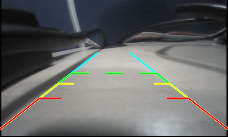
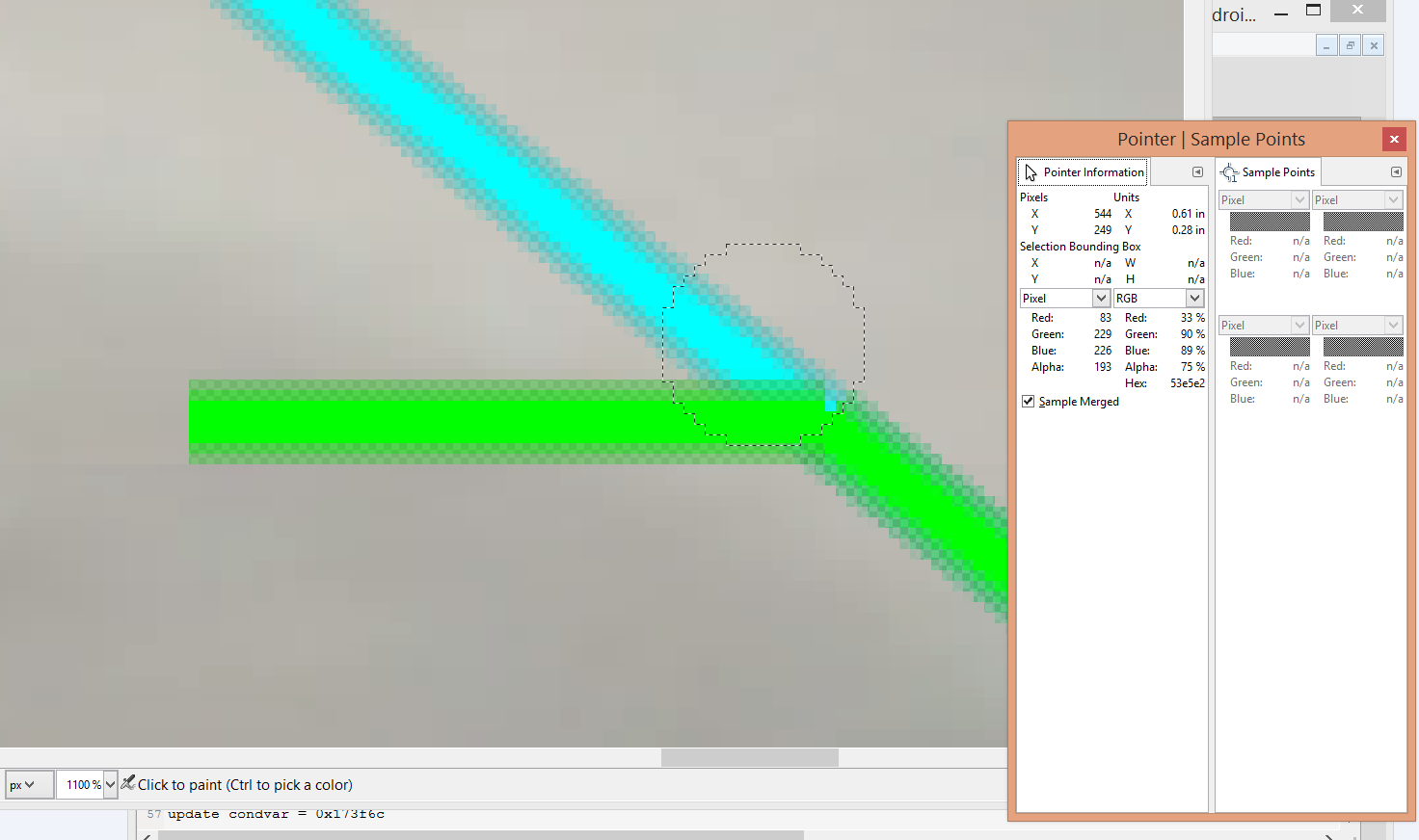
Wikipedia definition: a visual artifact in video display where a display device shows information from multiple frames in a single screen draw.

If tearing artifact is seen when displaying a captured stream (e.g. camera input), there could be a few reasons:

1. A partial frame was captured and displayed.

In this case, what being displayed is a combination of an old frame and a new partial frame. Visually, it would be a or more independent flickers.

The frequency of tearing would depend on: the number of buffers being used for capture; the frequency of partial frames.

2. The frames are being displayed out of order. — should be fixed in application

This is the most simple reason. This can be verified by checking if the sequence number of the frames being displayed/posted are still in order (assuming the frames are captured with a unique seqno given, respectively).

Visually, this would look the entire frame is pulling back and forth, not only one part of it; even it could be some kind of tearing, it is due to the display refreshing behavior. e.g. if the display refreshes from left to right, the lines which are being refreshed would look somehow tearing effect.

3. the composition rate or display rate is slower than expected.

In this case, a buffer is returned to capture hardware for new frame, while it is still being displayed.

Diagnosis: in crease the number of buffers. the artifact disappears; or increase the number of buffers hold by the application, the artifact will disappear.

4. capture hardware continues to write into a buffer, while it should not write.

in this case, the capture software is out of sync with capture hardware: the software considers a buffer is done and hands it over to display; the hardware keeps writing into it.

Visually, this will look like #3: constant tearing, or even ghosting effect.

Diagnosis: increasing the number of buffers will make it worse.

Artefacts resulted by transparency

Below are two snapshots from videos. the left is the bad case, where the green line is blurred; the right is the good case. The bad case gets reproduced when switching from Android auto to RVC mode.

the screen reflection confirmed this too. below is the images in 0/win-0.

Screen combined a few windows together. this is the top window. Its transparency is SOURCE_OVER.

win-5-1

Open it via GIMP,  the alpha of questionable area is not 255, although the majority of the image is with alpha 255. With SOURCE_OVER transparency,  the pixels will blend over the pixels underneath them.

analysis_gmp

These are the bottom windows for the bad case:

This is the bottom window for the good case:

win-6-1-a-a

For the good case, the alpha values of the bottom window (white) are all 1s (GIMP shows 1, not 0). As it is fully transparent, there is no blending occurring.

For the bad case, the alpha values of the bottom window (blue) are 255s. so the pixels on the top window (with a non-255 alpha value) will blend over with the bottom.

Solution:

change the top (RVC) window to “TRANSPARENCY_NONE”, and use alpha 255.

Jaggy artifacts (raw yuv file is important!)

Jaggy arfifacts are introduced by the mismatching between the mismatching of neighbouring pixels. In YUV color space, the focus is on Y component.

Some jaggy artifact is unavoidable. For instance,  when the WEAVE (field combination) deinterlacing is deployed, any change between fields will result “jaggies”, as the pixels in one field do not line up with the pixels in the other.

I met one issue, where UYVY output is good, while YUYV output shows apparent jaggies. First thing coming into my mind is: do the Ys get reversed while being output? Y0U0Y1V1–>Y1UxY0Vx?

The lucky thing is we can route the output to the input interface and capture the raw data to analyse. The raw data clearly shows that Y1,Y3, are not there, but Y0, Y2, are there for twice.

Use a hex editor to open the raw YUV file,

at address 0xC50, uyvy file shows “87 59 7E 5C”; yuyv file shows “59 87 59 7E”.

Cause of capture noise (1): power supply

dvd_colorbar
My set up is shown below.
Two boards, which are considered identical, except that: board A is coming with camera_A hard-wired, I reworked board B to have a RCA connector.
DVD player is external powered, camera can use the external power supply (camera_B), or battery inside(camera_C), or get the power from the board (camera_A).
There is no noise pattern seen with camera_A + board_A. However, when connecting board_B to
  •  DVD player, there are noise patterns captured. The fact is,
    • The DVD player works well with most boards, even the ones with the same decoder as board B.
    • Switch to another DVD player, the noise pattern is still there.
    • I did have some experience that increasing drive strength of the decoder avoided the noise patterns, on an old board. However, I have no idea how to avoid it on this board.
  • Camera B, noise pattern is seen, and even worse than DVD player: the pattern keeps moving vertically, and the capture module lost sync with the decoder frequently (when the noise pattern moves to the vsync interval, I guess).
I need eliminate the noise patterns of camera, to have some fair comparisons between camera A and camera B.
What I did:
  1. As the cable between cameras and decoder was re-worked by myself, I thought I brought some noises in while just twisting the wires together.
    • However, even I soldered the wires tightly, and made sure they were not exposed in the air (someone told me the wire would act as antenna if exposed in the air, and receive some noise signals, consequently), the noise pattern is still there.
    • Moreover, Camera_C doesn’t have noise pattern, even it is connected via the same wires.
  2. As camera_C doesn’t have this issue, we started looking into the power supply. A few options available:
    • Use the power from the board (not done,due to insufficient knowledge of the wire definitions on that board).
    • Use an alternate power supply, what we tried:
      • A 7.5V power supply with the same DC connector type (the noise is even worse, 3,4 stripes).
      • Rework the power cable to get power from laptop, via USB (failed, as USB can provide 5V maximum, but this camera requires a higher voltage (12V)).
      • Find a stable power supply.
        • Luckily, get one stable power supply. The connectors of this power supply is MOLEX connector. Therefore, cut and twist the wires of MOLEX connector with the camera power cable… and finally the noise pattern disappeared!!!!
Fundamentals:
  • DC connectors: Coaxial connector; Molex connector (4 pins, used for disk driver connectors).
  • USB connector pinout: Red is for VCC, black is for ground. White and green are for data.
  • Molex connector Pinout: yellow wire: 12V; red wire: 5V, black wires: ground.
https://i0.wp.com/www.shopaddonics.com/mmSHOPADDONICS/Images/AA4PFFPCBL.jpg
Update: there is one more cause which is worth to check: clock jitter resulted by wrong circuit design on the receiver side.
the two reasons above (low drive strength, or power supply) doesn’t introduce noise pattern if it is in Free run mode. If we do see noise even in free-run mode, check the circuit design.
See the image below. Removing R12102 and IC12102, and install R12100, will avoid the green line noise.
Screen shot 2015-07-10 at 11.02.35 AM
the IC is a bilateral switch, which makes the circuit tolerant of slower input rise and fall times when OE is low.

Artifacts(1): alias and chromatic aberration

SChromatic aberration/distortion
Chromatic aberration occurs along boundaries that separate dark and bright parts of the image.
  • Reason: the lens fails to focus all colors to the same convergence point.
  • avoid: It can be reduced by inrceasing the focal length of the lens.
Spatial alias
 an effect that causes different signals to become indistinguishable, which can occur in sampling or reconstruction process. If the image data is not properly processed, the reconstructed image will differ from the original image. Usually introduced when representing a high-resolution image at a lower resolution.
Spatial anti-aliasing
Remove higher signal components which can’t be handled properly before sampling at a lower resolution.
Anti aliasing makes polygon edges not jaggy but smoothed out. The level of anti-aliasing determines how smooth polygon edges are.

frame artifacts

Original problem: under high loaded CPU, some captured frames  have artifacts.
As the log “out of order field received” is printed every 1s100ms, it is obvious that a field might be missing/dropped somewhere.
In general, this capture driver works this way:
  1.  buffer handling.
    • The driver starts capturing into buffer when a field with specified field order(top, or bottom) comes. Then,  it switches to a new buffer after two fields have been captured into one buffer.
    • If the “field order” field indicates an unexpected value, the capture driver tears down the capture interface, and set frame flag of the current buffer to “error”, then set up a new buffer for future capturing.
    • The content of the “error” frame might be an old (good) frame (if the unexpected field order is detected right after switching to this buffer),  or the previous (good) field is combined/weaved with an fairly old field (if the unexpected field order occurs after a field has been stored in the buffer).  in the former case, the video has out-of-sequence issue while playing; in the latter case, the individual frame has artifacts.
  2. IRQ handling
    • The capture thread is “receive blocked”, waiting for an frame complete event(pulse).
    • After a frame is complete, ISR handler disables the capture interface and delivers this pulse to the thread, which will unblock the capture thread.
    • After the capture thread gets scheduled to run,  it sets up a new buffer for capturing,  and enable the capture interface (practically, the ISR is re-armed).
 It is impossible that an interrupt is not raised due to high-load CPU, and it is nearly impossible that ISR handler is not entered (as ISR handler carries higher priority than any threads). However, it is possible that the capture ISR is re-armed too late,  which leads to the field missing.
The kernel trace proved this assumption. According to the kernel trace,
In normal case,
  • the time between two NTSC fields (FE of the first one, FS of the second one) is 560us ~ 1ms;
  • the time between ISR returning an event and the event being passed to the thread is 5 ~ 10us;
  • once get a chance to run, the capture thread spends 60us to do it’s work (buffer handling, re-arm interrupts)
In the false case,
  • It takes too long for the sigevent/pulse  to be delivered to the thread (by kernel)  after 600us ~ 800us.
  • Screen shot 2015-04-01 at 1.05.53 PMor
  • the pulse is delivered immediately, and the thread gets ready soon. However, the kernel waits about 600~800us to schedule it to run.
    • in either case,  when the capture interface is reenabled by the capture thread,  it has missed the FS signal of a field.   and can only starting capturing until the FS signal of the next field arrives.
Screen shot 2015-04-02 at 9.42.02 AM
Screen shot 2015-04-02 at 9.50.16 AM
 After analyzing the kernel trace with one kernel expert, we found two reasons for this long time delay.
Reason #1:
  • The pulse was initialized with the priority “SIGEV_PULSE_PRIO_INHERIT”, which indicates the pulse inherits the priority from the process, and the driver “wants the thread that receives the pulse to run at the initial priority of the process”(per QNX document).
    • the pulse inherits a priority “10”.
    • There is a kernel thread with priority 10 is running on the same CPU when ISR handler returns a pulse.
    • The kernel sees a priority 10 pulse with SIGEV_PULSE_PRIO_INHERIT defined, and knows a priority 10 thread is running. Therefore, it doesn’t deliver the pulse to the thread until it knows the current thread is going to be blocked(the kernel is lazy, until it has to do something?)
This could be fixed by setting an explicit priority number to the pulse (the same as the thread priority).
Screen shot 2015-04-04 at 12.00.24 AM
Reason #2:
  •  Adaptive Partitioning is used( Note that APS isn’t a strictly priority-based scheduler). At some points, the partition  hw_capture_thread belongs to was out of budget, then hw_capture _thread waited too long to be scheduled to run.
    • the Partition Summary view shows  partition 4, to which capture thread belongs, has 3% budget but consumed 90% of cpu.  This is unreasonable.
    • Therefore, the system designer should reconsider which threads belong to which partition,  partition budgets, etc. They can consider moving the thread into a different partition, or changing partition budget, or marking thread as critical  – depending on what they are trying to accomplish with APS. “
Background knowledge:
Usually, ISR handler only do some register read/write, and whatever is mandatary. If there are more things to do, it schedules a thread to do the actual work: ISR handler returns a pointer to a const struct sigevent. Then, the kernel looks at the structure and delivers the event to the destination thread.